
Came out very nice. Has a angle iron edge. I used a Makita PW5001C wet stone polisher on the top surface – it came out beautiful.
Completed the workbench
June 27, 2010Announcing my new web site
June 17, 2010
Friends,
Please have a look a look at: http://nilno.com. I am will be announcing my site to the blogsphere soon and would welcome feedback from anyone and everyone.
owen
Ready for the big pour
May 29, 2010I built a platform to support the cement mixer and bought 25 bags on concrete.

The table is loaded with rebar and has angle iron on the edge….

…and laid in a space so MDF board can be mounted to the bench. Note the floating 2×4 in the back, that will be a depression in the concrete to holds pencils, etc.

Building form for concrete workbench
May 24, 2010
This is the makings of a concrete workbench. I made a recent addition to the wall behind the frame which are two 4×8 foot 16gauge steel sheets. The form is A LOT of 2x4s and plywood – this was built with an excess of wood to support the unbelievable amount of concrete that is going into the bench top. The bench will be 5 and half inches thick. A lot of rebar will be going into it so I can really pound on the thing.
Block diagram
May 15, 2010I made this to describe the overall system.
picture says it all
May 12, 2010
Well it aint much to look at
May 8, 2010
….but this component pretty much completes the laser cutting system. Its the motor speed control for the ventilation. I can now draw off all the fumes and oxygen generated when the laser is cutting.
Basically, the system is now fully functional.
Ventilation
April 25, 2010
This thing is pretty much ready to run. I’ve installed two tubes for drawing away fumes. One is attached to a plexiglas hood that sits around the cutting head, the other runs below the table. The blast gate on the lower tube helps regulate the draw in comparison to the top hood. Both tubes combine in the wall behind the back of the table, and the larger 12 inch tube runs up to the ventilation fan. The fan is wired up but what remains is to get a motor speed control, and put a hole through the roof with a roof cap.
Another pic of the table.
New optics
April 14, 2010
The new optics arrived. Their quality is great. The old optics are shown on the left, and you can see the new parts are a lot less bulky than my previous set. The vernier adjust is going to make height adjustment a lot easier.
Collimation. The first thing I did was adjust the collimator. The beam on lasers like mine spread out like a flashlight. The purpose of the collimator is to reduce beam divergence and to control the beam into a nice cylindrical beam, and is also useful because it allows you to expand the size of the beam (see: link). My collimator has two lenses and the precise distance of the two lenses influences overall expansion. To adjust these collimator, I rotated the laser sideways and pointed the beam at burn paper at a distance of 6 inches. Then I put a beam stop about 80 inches away and tested the diameter of the beam. A nice collimated beam should have the same diameter from a distance away. The collimator has some graduated lines on the side, and my burn card shows the beam size for each line. The graduated line for .5 inches seemed pretty good so I locked that position into place.

Centering the beam. Once the collimator was ready the laser was reoriented so the beam was shot downwards. The vernier adjust portion and cutting head was threaded on to the collimator. The optics assembly has a elbow bend with adjusting screws that allow you to center the beam. It was also useful to put some rusty carbon steel on the table, and used a cheap USB microscope to look at the position of the beam. I also used a bit of tape in the retaining ring of the cutting head, and hit the laser at low power for 0.04 sec duration to put a little hole in the tape. The beam was centered after a six or so iterations.
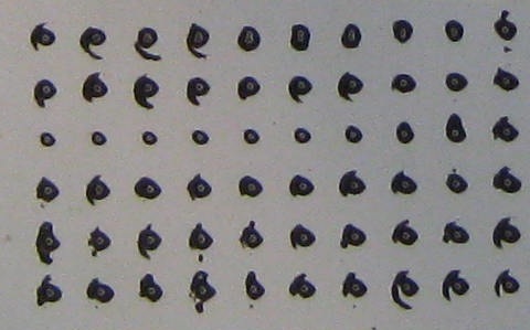
Height adjustment. After the beam was centered I started working on adjusting the height of the beam. This picture shows the goal of height adjustment. The issue is that the beam forms a waist and the most power of the laser occurs at the minimum waist diameter. The sweet spot of the beam waist can be placed in path of the beam by adjusting the height of the cutting nozzle.
To find the best height for minimum beam diameter, I used the thermally sensitive paper and looked at the beam diameter as a function of height. The first pass I took at this was by crudely changing the height while the shot a short duration laser pulse at burn paper. The smaller the dot on this burn test the better. This was repeated again to by starting at the general height from round one and using relative small turns on the vernier adjust. Up until this point the height adjustment was done without the copper cutting nozzle on the cutting head. I put the nozzle on the system and did more tests with the burn paper. If you look at this pic, you can see very odd things happen to the beam with nozzle on the cutting head. The beam is shifted around at the elbow using the adjusting screws until the crescent shapes around the central portion of the spot made by the beam is removed.
More electrical
April 12, 2010…installed 7 more quad boxes, 6 in the grinder/storage room.
